")
Building the TRF201 transmission
Exceptionally, I will not talk about the bodyshell. Well, not much, but still a little bit. On my TRF201 version, which is the original one, the Sand Viper bodyshell can fit like a charm. With any other XR or XM version, you need to use specific bodyshells since the wheelbase and the lower deck were modified. In my case, the bodyshell that came with the chassis doesn't need any care since it is in perfect condition.
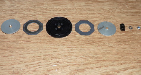
When you read the manual, which I highly recommend, you start with the first step. In fact, it is the most complicated of all since it is the build of the ball differential:
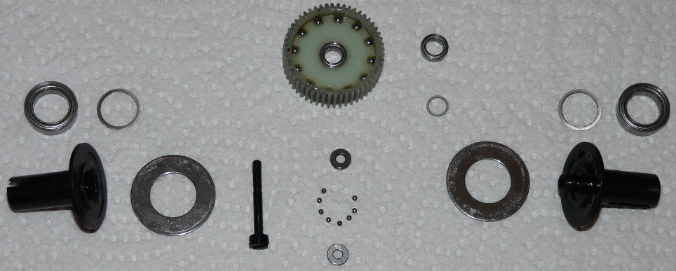
All parts on this photo make the TRF201 ball differential: the ball bearings, the spacers, the outdrives, the plates and the differential gear on which the balls have already been placed.
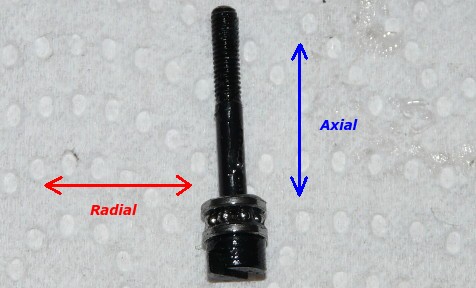
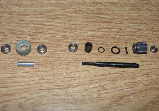
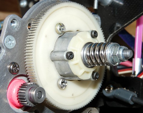
Differential screw
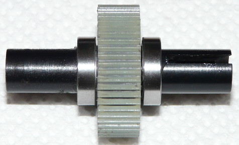
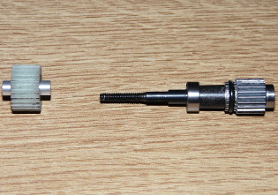
Built differential
On the first photo, you can see the diff screw with the two thrust washers and the 8 small balls that make a thrust bearing. In fact, it is a ball bearing without circumference rings. In fact, to be absolutely correct, a ball bearing should be called a radial bearing.
Pictures:
Ball bearing (no washer)
Thrust bearing
The difference between the two is important since they are meant to be used for different purposes:
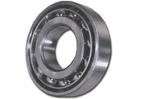
- Ball bearing
Physically, 2 rings (one small inside and one larger outside) and balls in between. Side washers are generally applied to close the bearing. This is what we use to replace the nylon or metal bearings on our RC models.
The ball bearings are designed for radial forces that push on the inner and outer rings. On the opposite, they can take relatively small axial forces (those pushing on the side washers).
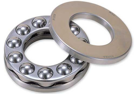
- Thrust bearing
Physically, 2 disks with balls in between with no inner or outer ring. Sometimes, the balls may be hold together with an internal disk (which does not apply here with our differential screw). Obviously, the thrust bearing can't take radial forces since balls are not protected. On the opposite, it will take axial forces like a charm, that is the forces pushing onto the disks (called thrust washers) along the axis of the differential screw.
JPrecisely here, being the differential screw, a thrust bearing is required. It is not the easiest thing to build at first sight, especially since the balls are very small (to give you an idea, the washer diameter is 3mm). However, this is only a question of technique:
Néanmoins, ce n'est qu'une question de méthode :
- place the first thrust washer onto the screw axis
- drop diff grease onto the thrust washer
- place a drop of diff grease on a screwdriver head: it will serve to capture each ball and to place them onto the grease you previously dropped onto the thrust washer
- once all the balls are in position, place the second thrust washer on top after having dropped diff grease on the face that will be in contact with the balls
In fact, it is much easier to perform than it seems, as long as you use the correct technique  . The differential screw then goes into the differential through one of the outdrives, the head of the screw being reachable once the differential is enclosed into the gearbox. You will only need to remove a driveshaft to get access to the differential screw in case you need to setup the differential stiffness.
About setting the differential stiffness. Unlike what you can sometimes read, never set the differential stiffness to the max and then loosen it by 1/4th or 1/8th of a turn: this is the best way to damage the balls by over-pressing them. The good technique is the one explained in the manual: progressively tighten the diff holding the outdrives until you can't move the differential gear anymore. The most difficult in setting the differential is to keep holding the outdrives while you check if the differential gear can still turn at the force of your fingers.
Next step, building the idler and counter gears before placing all the gears into the gearbox:
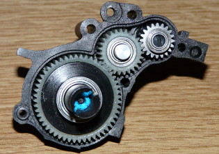
On the last photo, you can see the differential nut (blue alloy) under which is the differential screw and the previously detailed thrust bearing.
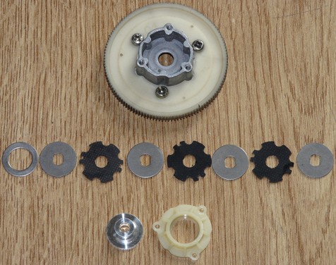
Last step of building the transmission, the slipper:
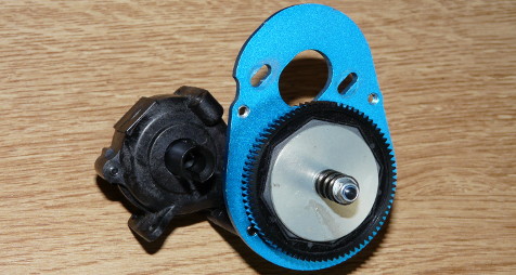
Here too, you'd better stick to the manual instructions to set up the slipper that will later need some adjustment in order to perfectly fit the track grip conditions. For pleasure, let's compare it with Tamiya's first slipper, the unit called Multi Disc Clutch on the Dyna Storm:
For more detailed information about how the slipper works and what it is made for, please read the article about my Porsche 935 Martini.
We are done with the TRF201 transmission. This is the most complex part of the kit assembly, but the very detailed manual instructions are there to help you clear these steps easily. Of course, the slipper and differential base setup are only a starting point and you will need to fine tune this setup according to your track conditions.
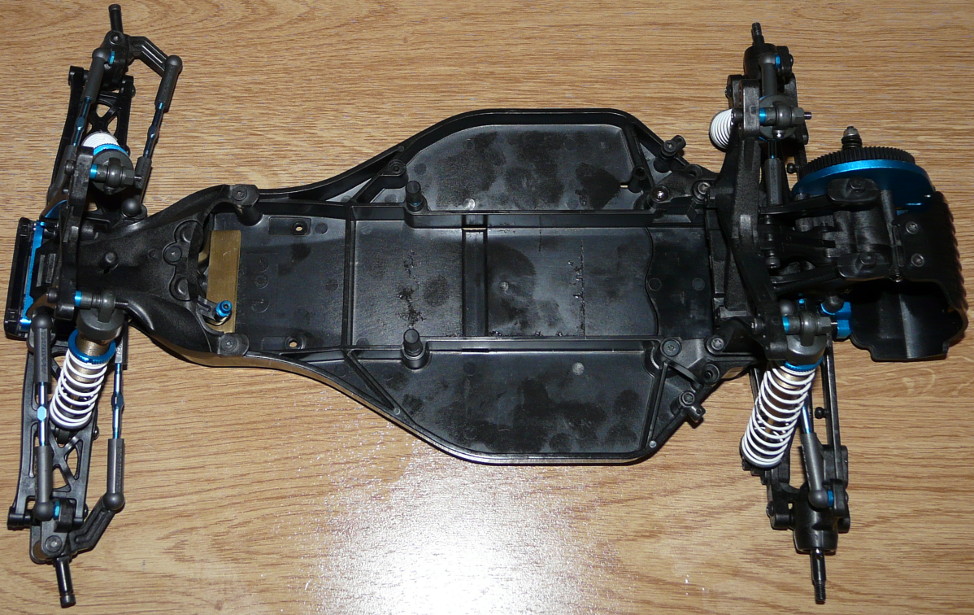
Building the TRF201 chassis
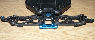
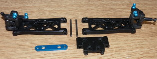
After the transmission, the next steps are dedicated to building the buggy rear drivetrain. We start with the upper and lower decks that will secure the rear drivetrain to the chassis bathtub:
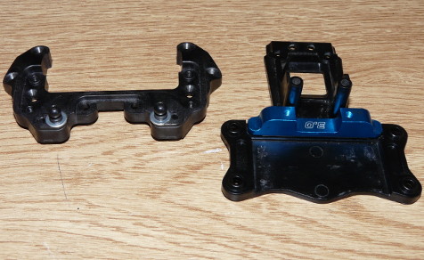
The blue alloy part you see is an option that came with my model. It replaces the stock plastic part to provide more stiffness to the anchoring of the arms. The engraved number 3.0 is the rear drivetrain toe-in angle.
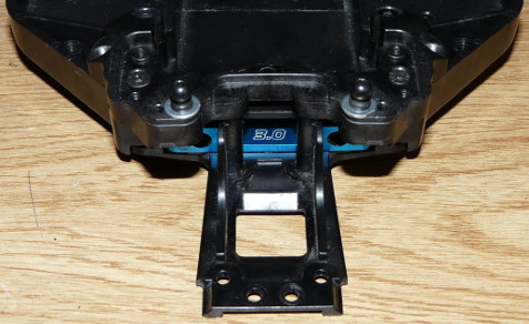
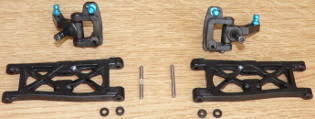
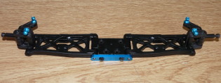
After assembling the arms, you place them with the rear drivetrain onto the chassis:
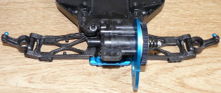
Here too, you can see another blue alloy part for anchoring the rear of the arms. Same role as the corresponding part anchoring the front of the arms, and same 3.0 degree angle engraved: these two parts need to provide the exact same toe-in angle. Any difference of angle between these two parts will automatically lead to an uncontrollable and malfunctioning rear drivetrain. You can increase the toe-in angle with alternative pairs of anchors up to 3.5 or 4.0 degrees, but you should never make it less since the chassis would be undriveable (in fact, no parts exist with less than 3.0 degree angle).
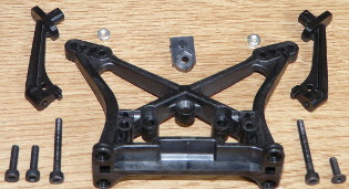
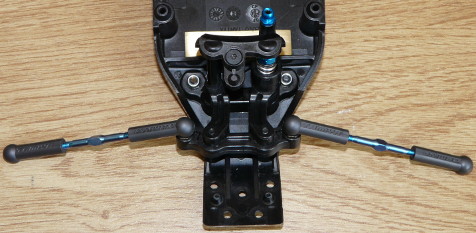
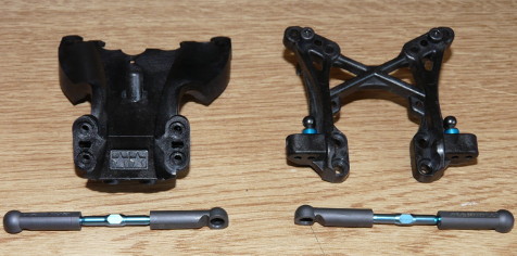
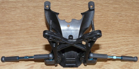
End of the rear drivetrain build with the assembly of the shock tower, the adjustable turnbuckles, the universal shafts, the wing stays and the motor guard:
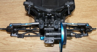
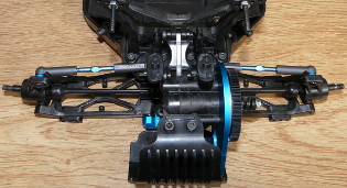
The rear drivetrain is now done, apart from installing the motor. So let's now begin with the front drivetrain build, starting with the steering system:
The lock nut and the spring you see under it is an adjustable servo saver integrated into the steering system. Once the steering system is installed onto the chassis, it is one of the most precise I have ever built: no play anywhere and a great smoothness. As for the bronze part you can see behind the steering system, this is a ballast of about 40g: it is meant to compensate the loss of weight on the front drivetrain since I will be using lighter LiPo batteries.
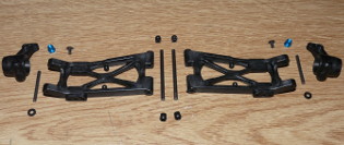
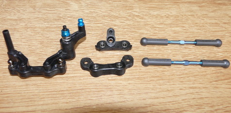
Next steps of the build, assembly of the arms, uprights, wheel axles (more on them later), steering cover and shock tower:
Somehow, nothing fancy here: adjustable turnbuckles, ball connectors and carbon fibered plastic everywhere. That's a TRF kit: adjustments are perfect (as usual with Tamiya) and everything can be set up and fine-tuned in every possible way. Turnbuckles dimensions are super precise at about 0.5mm: here, the manual is of great help since any length is represented at scale 1, allowing to check everything is precisely built as per recommendations.
Then, after building the TRF aeration dampers: