")
Ferrari 312T3 chassis
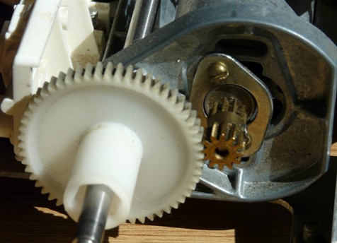
Apart from a full cleaning session, there is not much to do on this chassis that comes entirely setup with period equipment (apart from the receiver and servos). As usual, I will use modern electronics to preserve it when running. However, one element focused my attention: the transmission. I discovered this model had either a differential (spur gear with planetaries) or a fixed spur gear for a direct drive. The later is the one installed on the chassis I got and it will remain so since the 50077 planetary differential is pretty hard to find.
Based on my experience with my Tyrrell P34, I chose to install a Mabuchi 540 motor in order not to get asleep when cruising in the straight line. For this, you only need to replace the motor and change the pinion since the stock motor mount is made for a Mabuchi 540. In fact, the stock Mabuchi 380 motor requires a motor plate to be mounted (see the first photo).
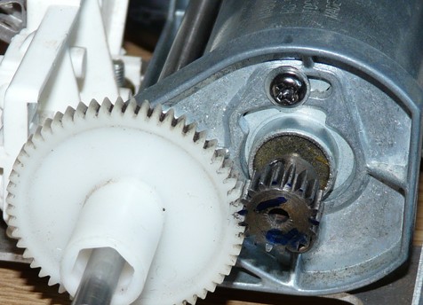
The motor pinion is an 18T (pitch 0.6) since it is the only one I had left in my spares (15T or 20T can also be used). However, the increased motor power may be hard to control due to the lack of differential. So, you'd better reduce the available motor power with your radio setup: only available on modern transmitters, look for End Point Adjustment (or EPA or even E-Point). Generally set as a percentage, it lets you set the range capacity of a servo (or of an electronic speed controller).
In private: for those of you who have already read my Road Wizard and Williams FW11B articles, the "motor plate" used to fix the Mabuchi 380 motor on this model should remind you something... Let me point out this is not a "foreign" part: that famous "magic" part used to make motor mounts more reliable from the F101 chassis and that was missing on the Road Wizard and Williams FW11B / Lotus Honda 99T was already existing since the late 70's.
View from the underneath, you can see the chassis design is not as basic as you may think at first:
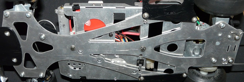
From this angle, you can immediately notice 2 distinct layers: the upper layer made of the electronics deck, and the lower layer that is the real chassis spinal column (here at the foreground). When having a close look at the photo, you can see the electronic deck only relies on 2 screws located on the central axis (the two darker screw heads on the photo): just remove them to check.
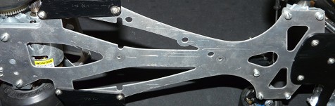
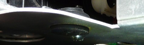
The second photo focuses on the rubber parts which are inserted into the chassis metal: inside this part called "rubber mount" in the manual, there is a metallic screw thread so the screw maintains the electronic deck. I didn't dare to remove this part from the chassis since I didn't want to damage an over 30 years old rubber part. This is why I used manual screen prints to show these "rubber mounts":
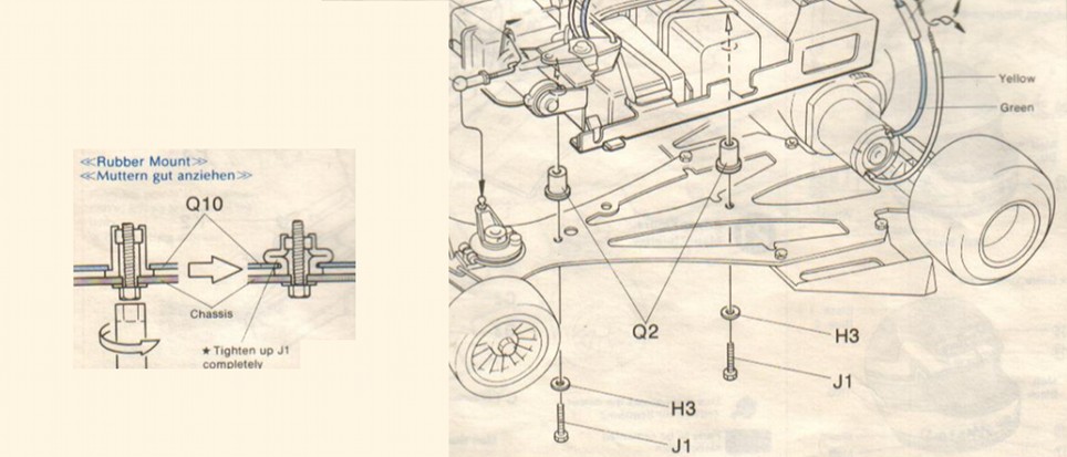
The material and the built made me wonder since it would have been much easier to use standard screws and bolts to fix the electronic deck to the chassis: as per logic, I supposed Tamiya had hidden a function into this specific way of building, but the manual gives no hint about it.
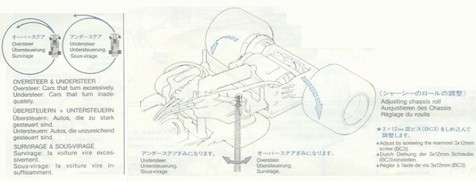
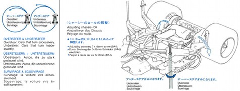
By chance, there are more recent Formula 1 in my collection, especially the F102 from my Footwork FA13 and the GroupC from my Jaguar XJR-12. On these models, one screw and a rubber o-ring are used to set the rear drivetrain softness, which makes the front drivetrain more or less directive (understeer and oversteer setup).
F102 chassis
GroupC chassis
So I think you can setup the Ferrari 312T3 chassis balance by stiffening or softening these two screws holding the electronics deck. This is a personal guess since there is no mention of this in the manual: to check if this guess is true, the track is the place to go. Unfortunately, driving such an old model requires a lot of caution not to damage it when the influence of this kind of chassis tuning mostly reveals when pushing the chassis to its limits. I consider it is wiser to keep up with the logical and likely, but still a guess.
Update: in a soon to be published article (about the Renault 5 Turbo), I could check this guess. The "rubber mounts" are not involved in anyway into the chassis flex. In fact, their role is limited to making the electronic deck "floating" so the chassis keeps the same flex abilities whatever the weight or its distribution onto the electronic deck.