")
Radio, servo and electronic speed controller for a Tamiya 3 Speed chassis
Some words to describe the electronic components I will use on my model: first, my Mountain Rider will be run in trail scale conditions, like my Mitsubishi Pajero, which means the ESC needs to offer the Drag Brake feature (that is brakes when the model is idle). The steering servo will need to be much more powerful than usual because of the weight of the model (much heavier than a standard model), also because of the big wheels (that require more torque from the servo to turn) and because my model will receive high grip tires (increasing overall effort on the steering system).
However, Tamiya's 3 Speed chassis is not conventional because it uses a gearbox: in order to select gears from the radio, one servo is dedicated to shifting gears so this servo requires one additional channel on the radio. In short, the required radio needs to be 3-channel, the first one for steering, the second for throttle (ESC) and the third for gearshift. Most radios on the market offer at least 3 channels (like my Flysky FS-GT3B et Turnigy GTX3), but most of the time, the third channel is only an on/off switch, meaning a two-position switch: not enough here.
Therefore, we need to look for 4 channel or more radios, but then, we enter the flying RC field. So let me warn you: an RC plane (or anything flying) pilot is someone demanding, very demanding for anything related to the radio. I am not going to detail this, but understand that a button is not just a button for an RC plane pilot: a button has precise characteristics like how it works, how to handle it or where exactly it is located on the radio transmitter. It may look weird and difficult to understand, but trust them, it is crucial for them. As a consequence, choosing this radio transmitter was somewhat more complicated than choosing regular “pistol” transmitters.
Here are the electronics I chose for my model:
 Radio transmitter
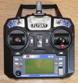
This is the 6-channel Flysky FS-i6 (also available as the Turnigy TGY-i6). Because we have long been using wheels instead of sticks, these things work with throttle on the left side (up and down) and steering on the right (right and left). The radio transmitter is a complex matter we will review more in details further in this article 
Servos
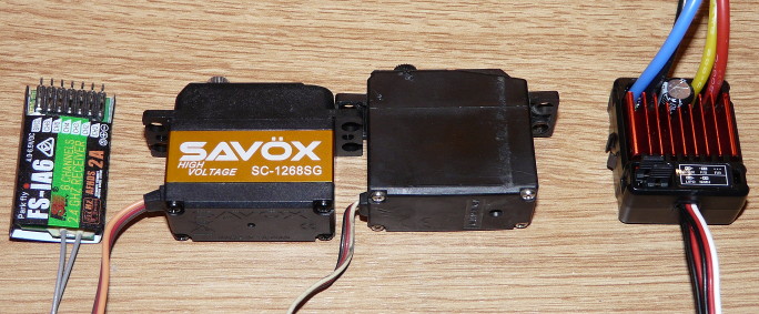
The steering servo I chose is a Savöx SC-1268SG: 25Kg under 7.4v, hence the HV label for High Voltage. “Regular" servos are meant to operate from 4.8 to 6.0v, which is a limit for torque power. To overcome this limitation, manufacturers now offer HV servos that can handle a higher voltage (7.4v, the voltage of a 2S LiPo battery pack): we will see further how to correctly plug this kind of servo. As for the gearshift servo, it is a Tamiya TP-S3003, a clone of the famous Futaba S3003: shifting gears does not require a lot of torque or speed, so this regular basic servo will perfectly do the job.
Electronic speed controller
I chose the Yeah Racing Tritronic 1060WP, one clone of the Hobbywing 1060WP. This ESC features the Drag Brake function and it is claimed to be waterproof. The BEC is limited to 2A, far from enough to power a high torque steering servo: on my model, this will not be a problem because the steering servo will be powered directly by the battery pack.
Motor
You already saw the standard Mabuchi 540 supplied with the kit: I will use this motor for the test runs because I want to know how the model handles in stock configuration. Afterwards, I will mount a Yeah Racing Hackmoto v2 35T motor.
Mechanism box
This is the official name of the box where electronics will be located on the chassis. The German translation calls it “RC box”, which is an even more accurate description. Could also be called “spaghetti box” due to the bunch of wires or “island of plastics and electronics in the middle of a metal chassis”: apart from the hard plastic bodyshell, that is where there is plastic (and electronics) on a 3 Speed chassis.
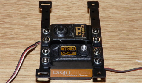
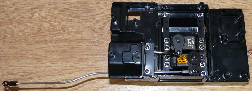
Nothing complicated for the moment: we first screw the two servos (steering + gearshift) on two mounts, taking care to respect the direction of the servos. The manual only recommends to fix each servo with only 2 screws: I chose to double it and make sure they wouldn't move, especially the hi-torque steering servo. Not sure it will make a difference, but the weight of 4 extra screws will not change much to the overall model weight anyway .
Everything gets into the casing and servo-savers and rods are installed. I used Hi-torque servo-savers, including for the gearshift servo that doesn't need it at all: as per the manual, both servo-savers should be the same, the one for the gearshift requiring to be cut not to hit the steering. I do not like to weaken a part that is meant to resist efforts, even here with the gearshift servo that will not make big efforts: this is why I chose to install a different servo-saver that didn't require to be cut. As for the steering servo-saver, I couldn't find any hi-torque servo-saver compatible with the low clearance in the mechanism box. Apart from the kit-supplied Tamiya Hi-Torque servo-saver that will work fine.
You can also see the rods, the shift rod being classic when the steering rod is extremely long (about 24 cm) and absolutely not straight. Now, here's one detail of the assembly and a view of all the electronics:
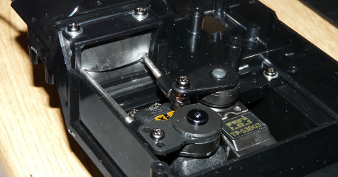
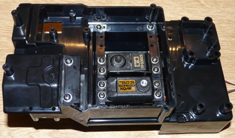
On the first photo, the interesting part is the sort of soft rubber curtain the steering and gearshift rods go through: obviously, the mechanism box was designed as dustproof in order to protect the electronics. Please note that dustproof does not mean waterproof, especially here because dustproof is a bit exaggerated. One advice: place a drop of grease on each rod where they go through the soft rubber sheet as it will greatly help the movement.
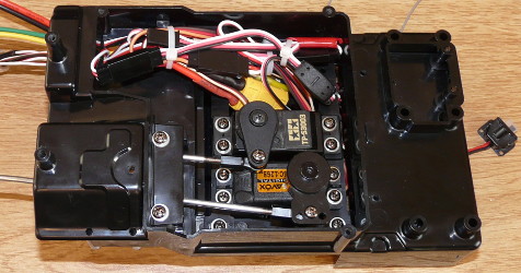
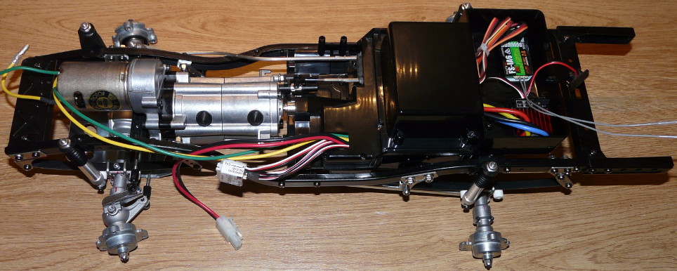
On the second photo, you can see the motor cables and the ESC power cables. Well, what you actually see are extension cables : the ESC is located in a tray which is under the platform you see on the right side of the servos and the motor is located at the very front of the chassis, that is about 25 cm away on the left of what is visible on this photo.
As mentioned just above, the ESC and the receiver take place in a dedicated tray located... on top of the mechanism box. I forgot to mention that the mechanism box was shown upside down until now because it was easier to install the servos this way...
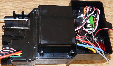
There is plenty of room in this tray, and yet, it will soon be filled: a 6-channel receiver offers 4 more possibilities to connect things .
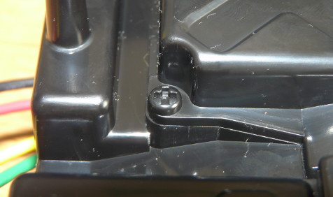
Last, one funny detail on the second photo: this is a screw. So what? Well, it is not a real screw but it is the molding of a screw that can be found on the lower side of the mechanism box. In fact, it can't serve any purpose, but it looks like Tamiya designers planned to place one screw there to secure the cover of the electronic tray, as the room left for a screwdriver shows. Then the designers probably thought that screw was useless so they removed it but they “draw” a fake replacement instead. Well, probably not. More likely, this screw was meant to be there when the part was designed and it was left there by mistake when the mold was made to produce the part. Ever since, the forgotten screw left its print on every mechanism box: that's what they call fame  ).
).
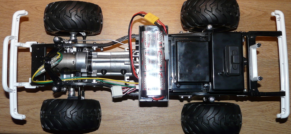
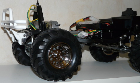
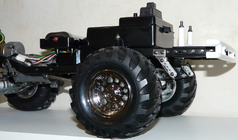
So, here is the mechanism box once installed onto the ladder frame chassis:
As you can see, it is not finished yet. But you can already see the steering rod connected to the steering pivot arm on the chassis and the gearshift rod yet to be connected to the gearbox. Precisely, this is the magic moment, the moment when you finally connect the gearshift rod to the gearbox, you remove the spacers, you switch the radio transmitter on and then the ESC on: right-left, the steering servo works like a charm. A slight push on the throttle stick: soooo great, only the rear wheels move which is normal because the “neutral” position of the gearbox is the second gear. Wunderbar as German friends say, now let's try the third gear: amazing, the rear wheels turn faster! About this, I immediately realized that the top speed in third gear should be lethal to the bodyshell if you don't brake before turning . OK, so let's try again the second gear in order to test the first gear. >>crack<< the first gear goes in like it does on a Jeep Willys when the driver forgets about the double-clutch: not good, and you'd better not insist unless you want to destroy the gearbox. The good new is that you know where to look to solve the problem: in the gearbox, between the first and second gears, or perhaps something related with the front driveshaft. The not so good news is that we need to disassemble the whole thing taking great care not to loose any part (and not forgetting to identify each part).
The explanation is that Tamiya supplies more 0.3 and 0.5mm spacers than required to build the model, the manual always recommending which spacer to use but also saying that more spacers may be required to better fit parts. Precisely, I had to use more spacers in order to eliminate play and better adjust gears on the main shaft. Actually, there shouldn't be any play at all on the main shaft, and there shouldn't be either close to the spur gear. This is important, in particular when installing the slipper clutch: this option seems to introduce some play on the main shaft (compared to the stock assembly), but spacers are supplied to eliminate the play. The 3 Speed transmission is a precision mechanism: it is important to take care that it works smoothly and without play.
The chassis build is now almost done: some elements are yet to be installed, like the battery tray, body mounts... and bumpers. Do you remember the one screw that was not meant to receive thread lock at the very beginning of th build? Well, that's now .
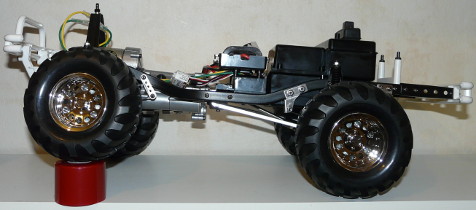
Here is the final result:
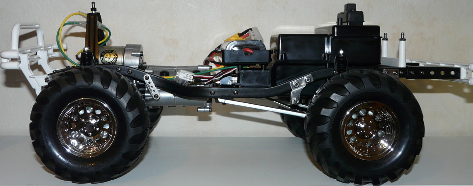
Accessing electronics is still possible: on the last photo, the protrusion you see at the back of the casing is the screw holding the cover of the ESC and receiver tray (cover on which is located the model switch). However, accessing the servo tray (steering and gearshift) is more complicated because it is under the chassis, protected by a cover that is not easy to remove.
For the fun, here's the classic articulation test using the cover of a Tamiya spray can:
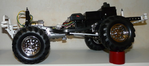
For your information, my Mitsubishi Pajero CC-01 chassis equals this, or does even slightly better .